The TransmitterRotationMatrix(TRM) seemed very confusing and after
many attempts to get the numbers used for this command from
the DC show I enlisted math and programming wizard Stuart Levy to
help. The two of us were able to analyze the system from his
point of view, which really helped. We came to the conclusion
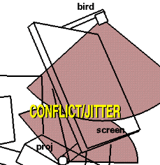
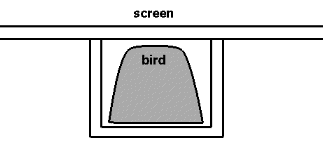
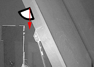
that the position of the 'bird' was very unadvantageous. I disconnected
the arm holding the bird and placed it so that the 'bird' was
right side up. A try at placing the 'bird' on the floor of the
pdesk next to the projector created a disturbance in the video.
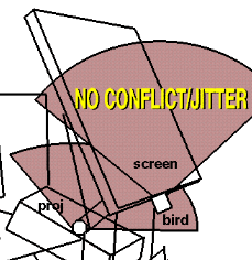
However lifting the 'bird' to a level above the projector right
under the screen did not effect the video greatly. I believe
that by having the 'bird' upside down it's magnetic field would
interfere with that ofthe projector, yet by having the bird pointed
away from the projector this interference was minimized.
By moving the 'bird' we were able to get stable nubers.By setting
the TRM to unity we were now able to collect numbers to create a new TRM.
We collected the values from 4 fixed points in space on the
cartesian axis of x,y,and z. By using these values we were able
to create a new TRM. This TRM worked great and the desk was functioning
very well except for a small detial - the scale was off. So
we set the WandSensorOffset to 0 0 0 inches and placed the
receiver on the three corners used by ProjectionCorners (ProjC). We then
entered these numbers into calder.config and that was solved.
Here is the calder.config options we used:
To calibrate a Desk (Immersa- or Porta-) for the
EVL Cave libraries, we need to:
The process of establishing a coordinate system and writing relevant
portions of a CAVE configuration file is automated by programs like
deskconf.
But, in case you'd like to go through the process manually, or understand
what the autocalibration programs do, here's how you could do it.
cavevars -caveconfig identity.conf
where identity.conf contains:
Now use e.g. cavevars' "wand" display to measure some points.
We need three 3-D positions to determine the coordinate frame.
Since we've set the WandOffset to zero, hold the wand's white
sensor knob (rather than its head) to the given spot to take a reading.
Measure, say:
Finally,
From these vectors we can build a coordinate system, but it's probably
not the one wanted for Cave coordinates. Those normally have Y vertical,
and the desk's screen is probably tilted.
So, measure the screen's tilt from the vertical -- 0 degrees if it is
vertical, 90 if horizontal facing up -- and construct Cave-coordinate direction vectors:
The (non-normalized) vector B - A gives the tracker's idea of the
width of the screen. Let Wvirtual be magnitude of that vector.
Measure the real-world distance between those same two points,
and let Wreal be the result in feet (or whatever you'd like
Cave units to be measured in). Multiply the vectors CaveX,
CaveY, and CaveZ by the factor Wreal / Wvirtual.
Re-invoke cavevars, specifying the new test.conf file.
Now you can simply hold the wand's sensor at the desired origin point --
conventionally I think it'd lie on the floor, a foot or two directly in front
of the center of the screen -- and note the reading. If that point is
beyond the tracker's range, just hold the wand in some other convenient spot,
say 3 feet above the desired origin, and subtract 3 from the reported Y value.
Edit test.conf, changing the TransmitterOffset values
to be the negatives of the values reported by cavevars at the
chosen origin.
Measure three points on the screen:
(If the tracker's range doesn't extend that far, you may have to measure
other points -- say the screen's lower left, lower right, and center -- and
extrapolate to find coordinates of the rest.)
Using the results, add two lines to test.conf:
ProjectionCorners screen7 llX llY llZ ulX ulY ulZ lrX lrY lrZ
The latter is needed for CAVE library version 2.6,
the former for earlier versions. (I'm not sure whether screen7 is
always the right choice, though it is for the two desks here at NCSA;
it should match whatever is mentioned in the Walls statement in the
existing /usr/local/CAVE/etc/cave.config file.)
Assuming you like the result, copy the TransmitterRotationMatrix,
TransmitterOffset, ProjectionCorners and ProjectionData
statements from test.conf to the systemwide cave configuration file.
Be sure there aren't any CaveRotation, CaveRotationMatrix,
CaveOffset, or CaveScale statements in it.
That's it. Note that deskconf doesn't work exactly as described above.
Rather than letting you place the wand at the adopted origin, it prompts
for horizontal and vertical distances from the screen's bottom center.
And rather than being restarted three times, it calculates how the
Cave libraries will transform the given points, and derives the
Cave-coordinate screen corners itself.
It prompts for environmental information, invites the user to
hold the wand's sensor blob to various points on the screen, and then
writes (to standard output) appropriate CAVE configuration commands,
suitable for inclusion in e.g. /usr/local/CAVE/etc/cave.config.
The only text written to stdout (as opposed to stderr) is valid CAVE config
commands, so you could test by invoking as
This version has been tried with CAVElibs 2.5.6 and 2.6.
It uses some internal CAVE functions to get the wall name, and to
get hold of the library's X display pointer so that it can open X fonts.
Both of these internal functions changed between 2.5.6 and 2.6, and
may presumably change again. If it breaks, look for code around the
If the tracker's output doesn't appear to be in feet, we emit a non-unit
CaveTransmitterRotationMatrix (which scales as well as rotates)
to compensate. I don't know whether this is a good idea, but haven't found
any bad effects so far.
There's not much provision for internal consistency checking, just:
Stuart Levy, NCSA, slevy@ncsa.uiuc.edu, Nov 1997.
Observations and Corrections
At first, I found it hard to work with the networked copies of
the CAVE libraries which were not using the tracker daemon,
which I was more familiar with. So I diverted the link to another file
named CAVE_AFS and installed a 'clean' version of the 2.5.6 Libraries.
I then set these up with the tracker daemon and changed the ports
on Calder to available. This enabled me to manipulate a barebones
hostname.config (calder.config) which would enable me to
troubleshoot the system. Now with the barebones configuration
the tracking was all over the place and very dificult to
understand. I first started manipulating the WandSensorRotation
and Offset - this would allow me to get something close but
did not seem logical that these offsets is what I should work with.
So now I focused on the TransmitterRotationMatrix and TransmitterOffset.
#idesk.config
TransmitterRotationMatrix 1.0000 0.0000 0.0000 0.0000 0.7071 -0.7071 0.0000 0.7071 0.7071
TransmitterOffset -0.12  7.90  -1.80 feet
ProjectionCorners desk -33.50 33.00 0.00   -33.50 72.93 -30.09   33.50 33.00 0.00 in

#corrections
#TransmitterRotationMatrix 1.0000 0.0000 0.0000 0.0000 1.0000 0.0000 0.0000 0.0000 1.0000
ProjectionCorners desk -5.5 0.0 0.0   -4.4 7.8 -2.0  5.0 0.0 0.0  feet
TransmitterRotationMatrix .016 -.053 1.0   -.009 1.0 .053   -1.0 -.01 .015
TransmitterOffset 0.0  0.0  0.0 feet

HeadSensorRotation 0 0 1 -90
HeadSensorOffset 3.75 0 -2.5 inches
WandSensorRotation 1 0 0 -30
WandSensorOffset 0 3 -7 inches
#WandSensorOffset 0 0 0 inches
The Math
this section is by Stuart Levy original at:
http://www.ncsa.uiuc.edu/~slevy/calibrate.html
If we assume that the screen's horizontal direction (e.g. its bottom edge)
is actually parallel to the floor, then it's natural to define Cave axis
directions as follows.
Measure reference points in tracker coordinates
To measure sensor coordinates, edit the cave config to
impose trivial sensor->cave transformations, and to report the wand
position as just where its sensor was. To do this by hand, it's handiest
to write a file containing these statements, then invoke e.g.
TransmitterRotationMatrix 1 0 0  0 1 0  0 0 1
TransmitterOffset	0 0 0
CaveRotationMatrix	1 0 0  0 1 0  0 0 1
CaveOffset		0 0 0
WandOffset		0 0 0
CaveScale		1
These points should all be within the tracker's range. (If the screen's
top edge is out of reach, try measuring the center of the screen.)
Given the identity tracker->cave transformations established by
identity.conf, we know where the tracker thinks these are.
Build orthogonal coordinate frame
Now establish the screen's X direction as the vector
ScreenX = normalize(B - A),
i.e. B - A normalized to be a unit vector.
The screen's Y direction is approximately
scrY = normalize(C - (B + A)/2).
If all were perfect, the scrY vector would be perpendicular to the
ScreenX vector, and we could use it directly in the coordinate basis.
It probably isn't, so subtract the component parallel to the X vector:
ScreenY = normalize( scrY - (scrY dot screenX)*screenX ).
ScreenZ = ScreenX cross ScreenY.
Calibrate tracker scale
Note that we'd ignored the scale of the cave. Conventional Cave units
are feet, but the tracker doesn't necessarily return measurements in feet
(at least ours didn't -- it was off by about a factor of two).
Scale isn't critical if you just care that things have the right orientation
and that the tracking matches the screen. But, if you'd like to get it
(more nearly) correct, you could compensate for the tracker's scaling as
follows.
Calibrate adopted origin
Next, choose an origin. If you're going through this process by
hand, it's probably best to make a copy of identity.conf,
say test.conf, and insert those Cave vectors into the
TransmitterRotationMatrix.
The vectors become the columns of the matrix;
thus if the components of e.g. CaveX are X0 X1 X2,
the TransmitterRotationMatrix line will have the form:
TransmitterRotationMatrix X0 Y0 Z0 X1 Y1 Z1 X2 Y2 Z2
Measure screen in Cave coordinates
Determine the coordinates of the screen's corners in the new
coordinate system. Again, if you're doing this by hand, it's simplest to
update the test.conf file to reflect the chosen origin and restart
cavevars -caveconfig test.conf.
ProjectionData screen7 both wall llX llY llZ ulX ulY ulZ lrX lrY lrZTest and install
If desired, remove the WandOffset from test.conf and re-invoke
cavevars -caveconfig test.conf.
If the calibration is correct, the wand's real-space position
should match its projected position on the screen as seen by someone wearing
the tracked glasses.
Stuart Levy, slevy@ncsa.uiuc.edu
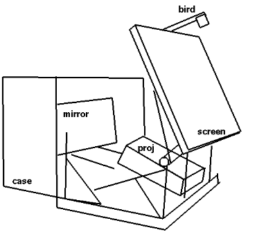
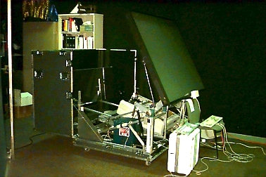
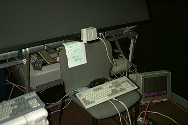
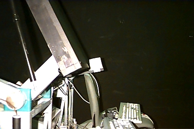
Images of Pdesk With Relocated 'Bird'
Where Do We Go From Here?
There are 3 substantial things which need to be performed
from this point.
Hank K built this stand to hold the 'bird'
(photo to come)
Here is what Stuart Levy put together for this:
deskconf calibrates tracking for a 1-wall (desk) Cave.
You can find a gzipped tarred source + CAVElib-2.6-binary package at
http://www.ncsa.uiuc.edu/VR/Apps/deskconf.tar.gz.
deskconf >> .caverc; cavevars
It does write both ProjectionCorners and 2.6's new ProjectionData
directives, so the config should work with both kinds of apps.
#pragma weak statements in the source.
last edited October 31, 1997
-----------------------------------------------------------
Tom Coffin                            tcoffin@ncsa.uiuc.edu

 National Center for Supercomputing Applications (NCSA)
 Virtual Environments Group
 University of Illinois, Urbana       tel: 217-244-3664
 M/C 476 - 152 CAB                    lab: 217-244-4913
 605 East Springfield Avenue          fax: 217-244-2909
 Champaign, IL 61820
                          http://www.ncsa.uiuc.edu/~tcoffin
___________________________________________________________